
Wiring and Fuse Sizing for Van Conversions
- Chris Wallace-Tarry

- Mar 2
- 22 min read
Updated: Apr 12
Wiring and fuse sizing is an essential element of your van build's safety. Improperly sized wires and fuses can cause very dangerous problems, including fires and electric shocks. This guide will teach you how to think about wire and fuse sizing, then give you a repeatable process for sizing wires and fuses that you can apply to any circuit in your van. All the information and advice we give is aligned with electrical safety standards given in BS 7671 (UK national standard for electrical installations), IEC 60228 (International Electrotechnical Commission guidance on insulated cables), and ABYC E-11 (American Boat and Yacht Council standard for electrical systems on boats).

Shane is an NCC-certified electrical installer. He has built, taught, and lived in campervans since 2019.
This post contains affiliate links. We may earn a commission at no extra cost to you. To understand our policies on content, affiliate commissions, and liability, please review our Terms of Use.
This article is designed to be informative only. Always consult a professional during your campervan electrical system installation.

In this guide
Before You Get Started
We have a couple of very useful tools here at The Van Conversion which will help you with your wire and fuse sizing. First, take a look at our wire size calculator.

Our wire size calculator uses the principles we go over in this article to calculate your wire sizes for you. It's useful to understand these principles, as you'll need to input some things into the calculator for it to work. Use it to check your calculations, or use it to give you all your wire sizes and check those against the calculations we explain in this article.
Second, Wireframe is our campervan wiring tool that makes every aspect of electrical system design a breeze. Especially relevant here is that it auto-sizes your wires and fuses based on the appliances you design them around. It's a fantastic tool, and very useful alongside our calculators when putting together your electrical system. Give it a try.

If you're looking for a deep dive on wiring types, connectors, and installation best practices, take a look at our ultimate wiring guide. If you're looking for details on fuse and breaker types and how to install these, our ultimate guide on fuses and breakers is for you.
Key Rules for Campervan Wire and Fuse Sizing
If you only remember one thing from this guide, make it this: a safe, reliable electrical system starts with correctly sized cable, and the fuse (or breaker) exists to protect that cable. Remember this: fuses protect wires, not appliances. In turn, wires are sized for two things: heat (ampacity) so the cable can carry the current safely, and voltage drop so the appliance works properly at 12V. We always size wires for the worst-case situation, meaning we choose the bigger cable demanded by our heat and voltage drop checks.
Most van wiring problems come down to a handful of simple mistakes; following these rules will help you avoid the big ones:
Measure cable runs as a round trip. Voltage drop depends on the total length of the circuit, which means the distance to the appliance and back again, not just the one-way run.
Size the wire first, then choose the fuse. Pick a cable size that keeps voltage drop under control. Once the cable is chosen, select a fuse or breaker that protects that cable.
On 12V systems, voltage drop matters more than you think. A circuit can be “safe” in terms of current carrying capacity and still perform badly if the cable is too thin, especially for fridges, heaters, pumps, and chargers.
When in doubt, size up. Thicker cable runs cooler and wastes less power. For DIY builders, oversizing cable is usually the easiest way to build in safety and avoid nuisance issues later.
Fuse close to the power source. Any cable leaving a battery or main positive distribution point should be protected as early as practical, so you are not running a long, unfused cable through the van.
Do not assume all breakers are suitable. If you use breakers instead of fuses, they must be correctly rated for DC use and sized properly for the cable they are protecting.
These rules are the backbone of the process below. Once you have your current draw, your round-trip distance, and your voltage drop target, cable and fuse sizing are reasonably straightforward.
Step 1: Identify the Circuit Type
Before you touch a calculator, you need to name what kind of circuit you are looking at. In a campervan, wire size is not one universal decision, because different circuits behave differently. A fridge circuit is usually a modest DC load that can be voltage-drop sensitive. An inverter circuit is a high-current DC feed where heat and fault current are the dominant risks. A solar circuit has two sides that behave completely differently. Correctly categorising your circuit is essential for proper wire sizing.
Every circuit is a path from a source to a load and back again. The circuit type tells you what the source is, how high the current could ever get, and what “good performance” means for that equipment. That's why professional guidance like Victron's Wiring Unlimited Book tends to separate DC distribution, charging sources, inverters, solar, battery links, and AC wiring into distinct categories.
Step 1 of the campervan wire and fuse sizing flowchart is therefore to determine the circuit type based on its source. Circuit types fall into one of the following categories:
DC Load Circuit
A DC load circuit is the most common type in a typical van. This is a cable run where the source is your DC distribution (usually a fuse box) to a single 12V or 24V appliance, then back to the negative return. You can usually spot these circuits because they are downstream of a fused distribution panel/fuse box and they terminate at something that does a job, like a light, fan, pump, heater, fridge, or USB outlet.

Charger Circuit
A charger circuit is any circuit where the source is a charger which feeds into the leisure battery. In vans this usually means a DC-DC charger or split-charger, a mains battery charger, or the charging function of an inverter/charger. You can identify charger circuits by looking for something that has a clearly stated maximum output current, and whose output wiring runs directly to the battery bank or to the main DC busbars.
Two things make charger circuits special. First, the worst-case current is usually the charger’s rating, not the typical current you see day to day. Second, charger circuits often have specific expectations about overcurrent protection location and sizing in professional guidance, because they connect energy sources to storage and can run for long periods. That is why standards-style documents talk explicitly about protection for charging sources and conductors connected to them.
Inverter Circuit
An inverter circuit is the high-current DC feed where the source is the battery bank (or main DC busbars) and the load is the inverter’s DC input terminals. This is one of the most important categories to get right, because a relatively normal inverter power level can translate into very high DC current at 12V.

Inverter circuits are not sized like typical DC load circuits. Voltage drop still matters, but the bigger issue is that you are dealing with high continuous current, high surge behaviour, and a need for appropriately rated protection and terminations. Guidance aimed at battery and inverter systems tends to treat this cabling as its own category for exactly that reason.
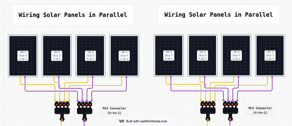
Solar Circuit
A solar circuit in a van is actually two different circuits that you should treat separately:
Array side (PV to charge controller): The source is the solar array, and the controller is the load. This side often runs at a higher voltage (especially with panels in series) and lower current than people expect.
Battery side (charge controller to battery or busbars): The source is the charge controller output, and the battery is the load. This side is usually lower voltage and potentially much higher current, especially with larger MPPT controllers.
You can categorise solar wiring by asking one simple question: “Am I on the panel side, or the battery side of the charge controller?” The worst-case current logic is different on each side, and the protection approach is different too, so it's important to get this right.

Battery Interconnect Circuit
Battery interconnects are the short, heavy links that connect batteries together in a bank, or connect a battery bank to busbars. These cables can carry current in both directions, and in fault conditions they can see extremely high current because batteries can deliver huge fault current into a short. You can identify interconnects because the source is the battery and the "load" is either another battery or the main DC busbar.
The practical implication is that battery interconnects aren't about typical load, but worst-case current and fault behaviour. This is therefore a key situation where we should be conservative with our cable sizing.
AC circuit
An AC circuit is any mains-voltage circuit in the van, typically 230V in the UK/EU and 120V in North America. In AC circuits, the source is either shore power or the AC output of an inverter. You can identify them by their AC sources and their termination at AC plug sockets, AC appliances, or the AC input of your battery charger.
The key point for categorisation is that AC wiring follows a different logic to DC wiring. In vans, AC cable runs are usually short enough that voltage drop rarely limits the design. Ampacity, correct protective devices, correct earthing arrangements, and compliance with recognised wiring practice matter more.
Step 2: Determine the Worst Case Maximum Possible Current
Once you've identified the circuit type in step 1, you then need to figure out the maximum current that could ever flow in that circuit. This maximum possible current depends on the circuit type. We'll base our maximum possible current on these rules:
Use the biggest plausible number, not the typical draw. We source this from labels and datasheets wherever we can.
Ratings given in watts must be converted to amps.
DC Load Circuits
Remember that these are individual circuits that run from a DC distribution point (a DC fuse box or busbar) to a 12V/24V appliance like lighting, a fridge, a fan, USB sockets, your diesel heater's 12V supply, a water pump etc.
If the load is rated in amps:
Use the manufacturer's stated current, usually referred to as the rated current, max current, input current, or current draw. If both 'typical' and 'maximum' figures are given, use the maximum figure.
If the load is rated in watts:
Convert watts to amps:
Amps = Watts ÷ Volts
Use the nominal voltage for your electrical system i.e. 12 or 24. For example, a 60W fridge on a 12V system has a rated current of 60/12 = 5A.
If the load has startup or surge behaviour:
Some DC loads briefly pull more current at startup; this start/inrush/surge/peak current is the maximum possible current for the circuit. Loads with a motor, compressor, or heater often have surge behaviour at startup. These would include things like pump motors, compressor fridges, and diesel heaters glow plugs. For devices like this, the manufacturer should provide a start/inrush/peak/surge current figure. If they don't, note that the load possibly displays inrush behaviour and we'll factor it into our fuse choice later.
Charger Circuits
This category includes DC to DC (B2B) chargers, split chargers, and mains battery chargers. It does not include solar charge controllers.
The key here is that chargers have an output side (to the leisure battery) and an input side (from the charging source). These are two different circuits, and the maximum current is different on each side.
Charger output side:
Use the charging device's rated output current as the worst case maximum current. This is the number that's explicit on the device label, i.e. a 30A B2B's rated output current is 30A, and a 50A battery charger's rated output is 50A.
Charger input side:
This is often higher than the output because of efficiency losses and because the input voltage can be lower than the output voltage. If the datasheet or product manual states a maximum input current, use that as your maximum circuit current. If no maximum input current is stated, calculate it like this:
input current = output current ÷ (efficiency ÷ 100)
and round up to the nearest 5A. For example, a 50A DC-DC charger with a 93% efficiency rating has an input current of around 50 ÷ (93 ÷ 100) = 53.76. Rounded up to the nearest 5A, we can take 55A as our maximum input current for this device.
Inverter Circuits
Inverters are the most common place DIY builders underestimate current, because the DC side currents are huge. To determine the maximum possible current in this circuit, we use the inverter's continuous AC output power (not peak power), given in Watts, and convert it to a DC input current:
Step 1: DC input current (A) = AC output power (W) ÷ DC system voltage (V)
Step 2: add headroom to account for inverter efficiency losses. Inverters should state efficiency numbers in the datasheet. We take this efficiency percentage, subtract 5% as a safety buffer, and use this percentage the same way we used efficiency figures in charger circuits:
Final input current = input current ÷ (efficiency ÷ 100)
So if we have a 12V 500W inverter with a stated efficiency of 90%:
Step 1: DC input current = AC output power (500W) ÷ DC system voltage (12V) = 41.66A
Step 2: Stated efficiency = 90%. Subtract 5 for safety buffer = 85%. Final input current = input current (41.66A) ÷ (efficiency (85) ÷ 100) = 49.01. We can round this up to 50A as the maximum input current for this inverter.
Solar Circuits
As we discussed in step 1, solar circuits can be divided into two parts:
PV side current (panels → controller)
Battery charge current (controller → battery)
PV side: panels into the controller:
Your “worst case current” here comes from the solar array’s short-circuit current (Isc) and how your panels are wired:
Series strings: current stays the same as one panel (Isc unchanged)
Parallel strings: current adds up (Isc sums)
Controllers and datasheets often explicitly warn that PV arrays with too-high short circuit current can damage the unit, and they publish a “max PV short circuit current” limit. That’s why Isc matters as a hard upper bound. So for Step 2 on the PV side:
Find each panel’s Isc on its label/datasheet
Multiply by the number of parallel strings
Battery side: controller output into the battery:
Here the worst case is simple:
Use the controller’s rated charge current (e.g., 30A, 50A, 100A).
Also note that controller ratings are typically stated as battery charge current, which is not the same thing as PV input current.
Battery Interconnect Circuits
For battery cables, the maximum possible current depends on whether it's a cable linking the battery to a distribution busbar (or shunt) or a cable linking batteries together in a parallel-wired battery bank.
Battery to Busbar/Shunt
This circuit can carry both charge current (inputs from the charging devices via the main busbar) and discharge currents (outputs from the battery to the main busbar.
Maximum discharge current: the sum of all DC inputs
Maximum charge current: the sum of all charger output currents that run simultaneously
To calculate the maximum discharge current of your battery circuit, add up all the DC input currents (loads) in your system. The most important one is the inverter's maximum DC input current (which also needs to be calculated for the inverter's circuits), followed by your biggest DC devices. The more DC loads you factor into this calculation, including small devices like lights and pumps, the more accurate the number will be. Once you have your discharge current, add a 10% safety buffer by multiplying the number by 1.10.
To calculate the maximum charge current, add up the charger output currents (calculated in the charger circuits section) which will run simultaneously. Once you have this number, add a 25% safety buffer by multiplying by 1.25.
From these two numbers, take the larger one as the worst-case maximum current for this circuit.
Battery-to-Battery Links
Battery-to-battery links are the cables (or busbars) that connect batteries together in a bank. The current they carry is determined by the maximum current the battery bank could accept, and how the bank is wired. Start by calculating these two numbers:

Max discharge current, Idis
This is the maximum current your loads could draw from the bank (inverter at full load plus any major DC loads that could run at the same time).
Max charge current, Ichg This is the maximum current that could flow into the bank from chargers that can realistically run at the same time.
Now set your battery bank's worst case current Ibank as the sum of Idis and Ichg. That’s the maximum possible current you’re planning for through the battery bank in normal operation.
Next, identify which wiring style you're using.
Daisy chain battery-to-battery cables: This is where you link batteries together with short cables, and the whole bank connects to the rest of the electrical system at one end. In a daisy chain, at least one battery-to-battery link can be forced to carry almost the entire bank current. So for daisy-chain cables, assume that the maximum possible current for each link is the same as the worst case current for the whole bank (Ibank).
Proper parallel bank using busbars:
This is where each battery has its own positive and negative cable to common busbars (or to posts), and the total path in and out of each battery is equal. This is the recommended way to wire parallel banks because it improves current sharing.
In this case, the highest possible current worst case would occur if one battery in the bank went offline:
Let N = number of batteries in parallel
Ilead(max) = Ibank ÷ (N − 1) (for N ≥ 2)
This gives a good maximum for each battery’s individual lead in normal operation.
AC Circuits
This is any mains circuit in the van. If it's an appliance, the maximum possible current is the stated current rating of the appliance. If this rating is given in amps, use that. If it's given in watts:
Maximum possible current in amps = current rating in watts ÷ 230V (UK) or 120V (North America)
If the AC circuit is powering a plug socket, we choose the maximum current that this socket will supply based on the maximum supply available to it:
If the socket is powered by shore hook-up:
The shore hookup current limit is determined by what campsites are capable of supplying. This is 16A in the UK, so you'll most likely use this figure.
If the socket is powered by your inverter:
Use the inverter's continuous output power (W) ÷ 230V in the UK.
Still figuring out your van electrics?
This is where most people get stuck — trying to piece everything together from scattered advice, second-guessing cable sizes, fuses, and system design.
The Van Electrics Masterclass walks you through the entire system step-by-step — so you can design and install it properly, with confidence.

Step 3: Choose Wire Carrying Capacity
Now that you’ve identified the circuit (Step 1) and calculated the maximum possible current it could ever see (Step 2), you can choose the carrying capacity of the wire you'll use in the circuit. As we go through this step, a key rule is that we oversize our wires by 10% for non-continuous circuits, and 25% for continuous circuits. We'll discuss this in detail later on.
Carrying Capacity by Circuit Type: DC Load Circuits
These are your DC 'appliance' circuits; lights, fans, pumps, heaters, fridges, plug sockets etc.
Start with the maximum current you calculated in Step 2 (nameplate current, datasheet, or watts ÷ volts).
Carrying capacity = maximum current x 1.1.
For appliances which are likely to experience an initial inrush/surge current (anything containing a motor, compressor, or heating element), it's a good idea to multiply your maximum current by 1.25 instead of 1.1.
For lights, multiply the maximum current by 1.25, as they can run for a very long time.
Charger Circuits
We discussed how to calculate the maximum output and input currents of chargers in step 2. Because chargers are considered appliances that might run continuously for more than 5-6 hours, we use a higher buffer than other circuits, giving a 25% safety margin:
Carrying capacity = maximum current x 1.25
Inverter Circuits
We calculated the maximum current in step 2 using the inverter's stated power in watts and its efficiency rating. Once again, we multiply this calculated maximum current by 1.10. Manufacturers often recommend a fuse size in the inverter manual or datasheet; if your calculations are correct, this fuse size should be slightly smaller than the carrying capacity you've calculated.
Solar Circuits
These are the circuits between your solar panels and the charge controller, and between the charge controller and the leisure battery. In step 2, we said that on the panels-to-controller side, we calculate the maximum current by multiplying our solar panels' stated short circuit current (Isc) by the number of parallel strings in the solar panel array. For the controller-to-battery side, we simply use the charge controller's rated charge current.
Because your solar charge controller also runs continuously for more than 5-6 hours, we also use a 25% safety buffer. So, for both sides of the solar circuit, take your calculated maximum current, and multiply it by 1.25 to get your wire's desired carrying capacity.
Battery Circuits
This is your battery-to-busbar circuit, the main cable that goes from your battery to everything the battery powers. We already worked out our maximum battery current in step 2, defining it as either the maximum charge current + 25%, or the maximum discharge current + 10%, whichever is larger. This final number is our wire's desired carrying capacity.
When fusing this circuit, the simplest thing is to use a battery terminal fuse, which is fixed directly to the battery terminal. If you're not using a battery terminal fuse, you'll be running a cable from the terminal to a fuse, and from the fuse to your busbar. Both of these cables need to match your calculated carrying capacity, and make sure you keep the fuse as close as possible to the terminal; European ISO/RCD law for marine systems requires the fuse to be no more than 200mm from the terminal, whilst US ABYC requirements have it at 7 inches [source].
AC Circuits
As we said in step 2, we calculate the maximum current of an AC circuit based on whether or not it's powering an appliance or a socket. If it's an appliance, we calculate the maximum current by taking its rated power in watts and dividing it by 230 in the UK or 120 in the US. Once we have this number, we add a 10% safety buffer by multiplying it by 1.10.
If the AC circuit is powering a plug socket, we choose the maximum current that this socket will supply based on the maximum supply available to it:
If the socket is powered by shore hook-up:
The shore hookup current limit is determined by what campsites are capable of supplying. This is 16A in the UK, so our carrying capacity is 16 x 1.1 = 17.6A.
If the socket is powered by your inverter:
Use the inverter's continuous output power (W) ÷ 230V in the UK or 120V in the US. Multiply this by 1.1.
Step 4: Choose Wire Size based on Voltage Drop
We're now ready to choose a wire size. For this, we use a sizing table where the wire size is determined by the wire's carrying capacity against the length of the circuit. The length of the circuit is important because voltage drops off with increasing cable length. We can mitigate voltage drop by increasing the size of the cable.
For essential circuits, we set an acceptable voltage drop of 3%. This is for all circuits that you don't ever want to fail; all chargers, battery circuits, and essential appliances like your fridge, heater, water pump etc. Non-essential circuits, which might include your inverter, plug sockets, and non-essential appliances like lights, can take a slightly higher voltage drop of 5%.
Determine the circuit length (one-way), and then use the wire sizing chart below to choose your wire size. Be as accurate as possible when measuring the one-way length of your wire, and if in doubt, add a small margin of error.

This table assumes a 3% allowable voltage drop. If you decide that a 5% voltage drop is acceptable for a circuit, move one column to the right when choosing cable size. If you find yourself looking for a carrying capacity that's between the standard capacities in the table's columns, round up. Remember that our wire sizing calculator does these calculations for you; use it to verify your calculations.
With your wire size chosen, we can now check it against its heat-carrying capacity.
Step 5: Check Wire Size Against Ampacity
Now that you’ve got a wire size, we need to check it against ampacity. Ampacity is simply the maximum current a cable can carry continuously without overheating. In a campervan, overheating is usually caused by a cable that is too small for the current, installed in a way that traps heat, or terminated on connectors that cannot tolerate the temperature rise. BS 7671 describes this as the cable’s current-carrying capacity Iz, which is defined for continuous service under the relevant installation conditions.
Practically, we use an ampacity reference table to check our cable size choice based on ampacity. We determine the ampacity of the circuit as follows:
Conservative Assumptions we Use for Campervans
Ampacity is not one fixed number. It changes depending on how and where the cable is installed. For this guide, we use assumptions that are realistic for DIY van builds and deliberately conservative. These assumptions are called deratings:
Copper conductors only, flexible stranded cable (typical van and marine cable).
Positive and negative run together (so conductors are effectively bundled).
Enclosed vehicle spaces with limited airflow, often routed through furniture voids, conduit, trunking, or split loom.
30°C ambient reference, with the understanding that vans can exceed this, so “conservative by default” is sensible. (BS 7671 uses correction factors for ambient temperature and grouping for the same reason.)
Cables are bundled, and bundling reduces ampacity. ABYC explicitly requires reducing allowable ampacity when conductors are bundled for any meaningful distance.
If your installation ends up better than this (short runs, plenty of air, no bundling), your real-world ampacity will usually be higher. However, we still use these conservative assumptions to ensure we don't under-rate the circuit.
Base a Cable's Ampacity on the Lowest-rated Component of the Circuit
Your cable insulation might be rated to 105°C, but the rest of the circuit might not be. Heat generated in the conductor is transmitted into lugs, fuse holders, breakers, busbars, and device terminals. A good practical rule is:
Use the lowest temperature rating of any element in the circuit as your governing rating.
ABYC requires minimum conductor temperature ratings and makes temperature rating a core selection criterion.
What to do in Practice
Check what is printed on the cable jacket (60°C, 75°C, 90°C, 105°C).
If your fuse holder, breaker, busbar, shunt, or device manual specifies a lower conductor temperature rating, treat that as the limit.
If you cannot confirm ratings, default to a conservative ampacity (90°C) rather than assuming the highest.
In the ampacity reference table below, find the cable size which matches your circuit's maximum current (calculated in step 3) for the ampacity you've decided on.
Always round up to the next standard conductor size if your maximum continuous current falls between the capacities of two cable sizes in the table.

This ampacity table is published by Blue Sea Systems, a manufacturer of marine electrical systems. We're interested in the right-hand table, as we assume that most cables in a campervan are bundled or stuck in conduits or behind insulation. The 'EngRm' columns are marine-specific, detailing ampacities for cables in a boat's engine room, so ignore these.
Using the above table, look in the column specifying the ampacity of your cable. Go down the column until you find the carrying capacity you've selected for that cable. Then, check against the left-hand column to find the cable size that matches that carrying capacity and that ampacity. Always round up if you find yourself between cable sizes.
You might now have two different cable sizes based on the circuit's maximum current: one determined by voltage drop, and one determined by ampacity.
Step 6: Final Wire Size
If the wire sizes you came to in the last two steps differ, the final choice is simple:
Choose the larger wire.
This is the final, conservatively chosen wire size which is practically defensible based on the calculations we've gone through.
Step 7: Decide How the Circuit Will Be Protected
Now that we have a wire size, we're ready to fuse that wire. First, you need to decide how you will stop that circuit from ever overheating in a fault or sustained overload. This is what “protection” means: a fuse or circuit breaker is selected and placed so it will open the circuit before the cable can be damaged by excessive current.
Choosing Between a Fuse, a Breaker, or Upstream Protection
Option 1: Protect with a fuse
Use a fuse when you want the simplest, cheapest method of protection, and you do not need the protective device to act as a switch. In campervans, fuses are the default choice for:
battery-to-busbar and battery-to-distribution feeds
inverter feeds
charger feeds
solar controller output feeds
most DC branch circuits via a fused distribution panel
Fuses are straightforward to size and widely available in formats that suit everything from small branch circuits to very high-current feeds. They're also significantly cheaper than breakers.

Option 2: Protect with a circuit breaker
Breakers work like fuses, except when they trip, a switch flips rather than a metal filament melting through. This switch can be reset, as if you could somehow repair the filament in a blown fuse. Use a breaker when you want protection that is resettable, or you want the device to double as an isolator for maintenance and troubleshooting.

Read more about fuses and breakers in our detailed guide on the subject. For more information on RCDs and other kinds of AC breakers, check out our guide on shore power.
Option 3: Use upstream protection
Upstream protection means a cable is already protected by a fuse or breaker earlier in the system, so you do not need an additional protective device on that specific segment. This is appropriate when:
the cable run is entirely downstream of an existing protection device, and
there are no unfused branches taken from the cable before the protected device
A practical rule for DIY builders is simple: if a cable leaves a battery, busbar, or any other source of power, and you cannot clearly point to the device that protects it, then it is not protected and it needs a fuse or breaker near its source.
Step 8: Select the Fuse Size
We can now choose the fuse (or breaker) rating that will protect the cable feeding that circuit. Keep these two key points in mind, as they make this step simpler than it seems:
A fuse's job is to protect the wire from overheating, not to "save" the appliance.
We size the fuse slightly smaller than the wire, so it trips before the wire fails.
The fuse sizing calculation is simple:
For continuous loads (chargers), we size the fuse 10% smaller than the wire.
For non-continuous loads (inverters, appliances, AC circuits), we size the fuse 5% smaller than the wire.
In all cases, round up to the nearest standard fuse size once you've calculated your desired fuse capacity.
If a manufacturer gives a specific recommended fuse, simply use this, then make sure your cable selection in Steps 5–8 still satisfies ampacity and voltage drop. (This comes up a lot with inverters, inverter/chargers, and solar controllers.)
You should now have decided on a fuse size and a wire size for all the circuits in your van. You can check your calculations against our own wire size calculator. That calculator uses the same logic and conservative buffers that we've gone through in this article, and also contains all the useful tables in one place. You can also use Wireframe, which auto-sizes your wires and fuses depending on the appliances you install.
Converting Between Metric and AWG
We reference wire sizes in metric units (cross-section in mm²) in this and other articles on our site. This is because it's the standard for wire sizes in the UK and Europe. If you're in North America, you'll be using the American Wire Gauge (AWG) instead. To convert between metric and AWG, use the table below:

The conversions aren't perfect, with AWG not mapping perfectly to metric increments. As always, be conservative, and round up, never down.
Final Thoughts
You should now understand the process of safely sizing fuses and cables for all the circuits in your van. These rules and calculations are factored into our very useful wire size calculator, but using this calculator still starts with knowing the size of the fuse that will protect the circuit; the fuse size in amps is the number we use for the circuit's load in amps in the calculator. For a more detailed look at fusing and the theory behind the calculations in this article, check out our ultimate guide to fusing. We also have detailed guides on the principles behind wiring and on shore power, including a breakdown of shore power consumer units and the different breakers you might use in these.
Still unsure how to design your van electrics?
Start with the free wiring diagrams below.
Want to build your van electrical system properly from start to finish?
The Van Electrics Masterclass shows you exactly how to design and install a safe, reliable electrical system — step by step.
Until next time.

